PC Engine/TurboGrafx Region Modification (HuCard Slot Mod)
The modification described here is not for the faint of heart, those with weak constitutions, or shakey hands. If you can handle a soldering gun, simple power tools, and wire cutting and stripping, this is something you can do. But if you can't handle a snap-together car model, stop what you're doing, drop me an e-mail, and go watch a movie before you do more damage than I can bail you out of. But this is doable even if you're not sure you can handle it. I'm going to demonstrate the mod step-by-step here using the Japanese CoreGrafx system. It's basically the same as all the other systems that have HuCard slots and is also one of the more challenging ones due to space constraints.
What is this modification?
This modification allows you to play all regions of HuCards on either a US or Japanese system WITHOUT the need for an external adapter like the Kisado Converter. Normally that's locked out since pins 15-17 and 19-23 are flipped between the regions. All systems with a HuCard slot will work with this mod, the only difference being that Japanese systems will need pin #29 on the Hu6280 processor grounded (this will be covered later). You can use either a PCB version which I have available for $15 (plus shipping) or get an 8PDT switch. The process described here involves the PCB version. Also, although the mod shown here is on a CoreGrafx, it should work for any of the PC Engine/TurboGrafx family members. If you want a PCB or want me to do the mod for you ($35 for the small systems, $40 for the Duo size stuff, prices include shipping), drop me an e-mail at dean@multimods.com
What tools will I need?
|
|
|
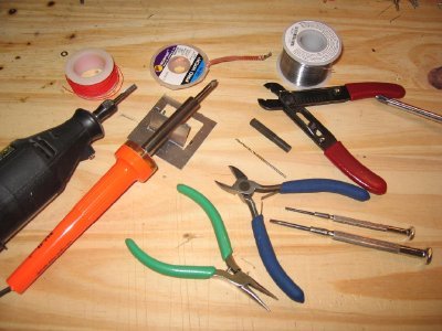 |
The bare minimum is a soldering iron, wire cutters, wire stripper, the 4.5 mm security bit, and a drill. But what you should have is shown here. That's a spool of wrapping wire (30 gauge stuff), Dremel tool with cutting bit, soldering iron, desoldering braid, wire cutters, wire stripper, needlenose pliers, 1/16" drill bit, wire solder, precision screwdrivers. You may be able to get away with some but not all of these items, but trust me, your life will be easier with all of them. And a glue gun. And some files. Oh, and aviation shears. Yes, I'm serious. |
|
|
|
|
|
A note on some of these items.
Solder Braid: This stuff is for the mistakes we all make. Too much solder? Heat this stuff up on the solder you want to remove and watch it adsorb onto the solder braid.
Dremel Tool and bit: Here's where it's preference vs. convenience. A Dremel Tool is great for a ton of stuff, not just this project. Here I show one of the cutting tool bits, more of a grinding wheel, really. I use it to rough out holes, shape edges, etc.
Soldering Iron: You don't need a Weller WES51 to do the job, a standard old Radio Shack $10 soldering iron is plenty good enough to do this mod cleanly. The dual 15/30W soldering iron is a decent option for this application. Make sure you get the finer 15W tips though as you'll need them when doing the pin #29 grounding. The soldering iron shown here is a $16 Weller you can find at Home Depot.
Small Screwdrivers: Radio Shack and many other stores sell 6 piece precision screwdriver sets. I use them for other applications too, such as wrapping the wire around connections and even as soldering tools.
Let's start!
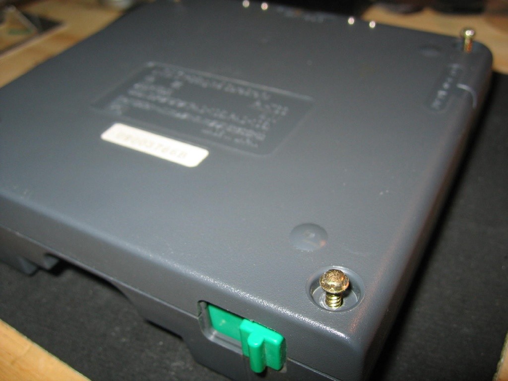
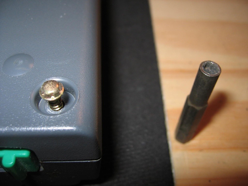
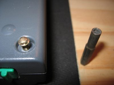
This is the bottom of your CoreGrafx. Four screws. Get'em out with that 4.5 mm security bit (available all over eBay). If you're doing this mod on a PC Engine Duo/DuoR/DuoRX, you'll need a Torx #10 security bit. It's a 6-pointed star with a hole in the middle (that's the "security" part of the thing). One thing to be aware of with the CoreGrafx and CoreGrafx II: in the back of the console, where the expansion port is, are 4 small metal dots that have a spring action. When you remove the bottom cover, keep the metal shielding in place or these will pop out and you'll curse like all get-out.

Cutting the pins on the cart slot
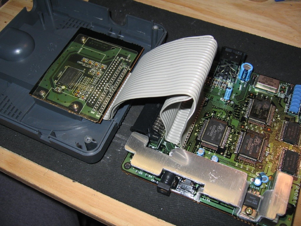
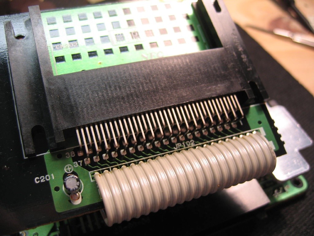
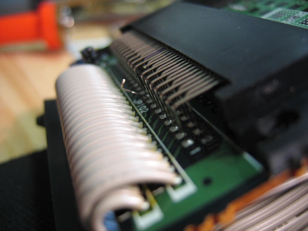
OK, now you have the thing apart and you should see the works. Pull the system apart gently and then unscrew the cart slot piece from the upper cover of the system. Turn the system so the cart slot is facing you as shown in the second picture below. The slot has 38 pins that are bent at 90 degrees from the PCB itself. Now looking at the slot you'll see the edge pins are numbered, going from 1 to 38 from right to left. What you should do is count from right to left and find pin #18 near the middle. You'll notice on the PCB that the pin has more green around it and that's because it's grounded. This pin will NOT be cut. I usually mark it so I can easily spot it as you'll see a couple pictures down.


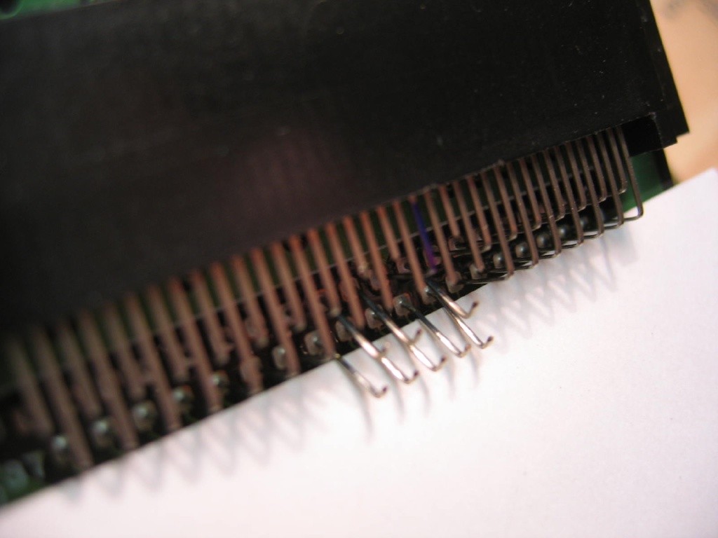
Using the wire cutters, snip pins #15-17 which are the three to the right of pin 18, and then pins 19-23 to the left of pin #18. The way I do this is to cut the "long" pins first, those that are closest to the edge of the PCB. So that's pins 15,17,19,21,23. Specifically, I cut them such that there is about 1/16" of the bend left so I can hook the wires onto them in the coming steps. You can see this technique in the following pictures. Cutting pins 16, 20, and 22 nearest the cart slot next should give you 8 total cuts. Then, take a pair of needlenose pliers and bend up about 1/16" of the pins left on the cart slot so they have little hooks on them, similar to those on the PCB side. Again, you'll see the utility of those later.


Wiring the pins on the system
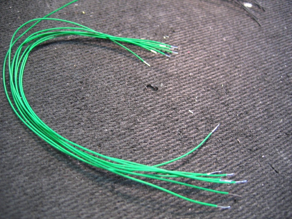
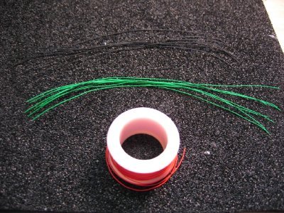
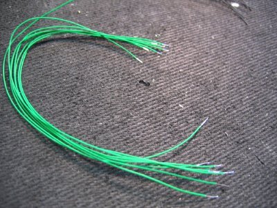
So now you have 16 pins to wire up and you'll need 16 wires to do this. Grab yourself some wrapping wire which is really skinny stuff, 30 gauge. I prefer to have two different colors so I can wire the PCB side one color and the HuCard slot side another. Believe me, it helps. Take the wire and cut 8 pieces of each color (or 16 pieces if using only one color) about 6 inches long each. Then strip the one of the edges to about 3/16" of bare wire and the other end to be around 1/16-1/8" of bare wire. The longer wire will be the end we wrap around the pin and the short end will be going to the region PCB you have. Here's some pics of the wires cut and stripped.
|
|
|
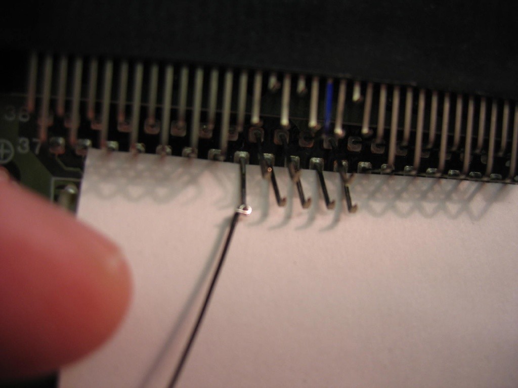
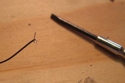
Now you need to curl the long ends of the wires to be little loops as shown to the right. I do this using a smaller screwdriver to bend the wire back about 180 degrees and then push the loop to a circle using my fingers. This gives you a hook to catch onto the pins we cut earlier. |
|
|
|
 |
|
|
|
|
|
|
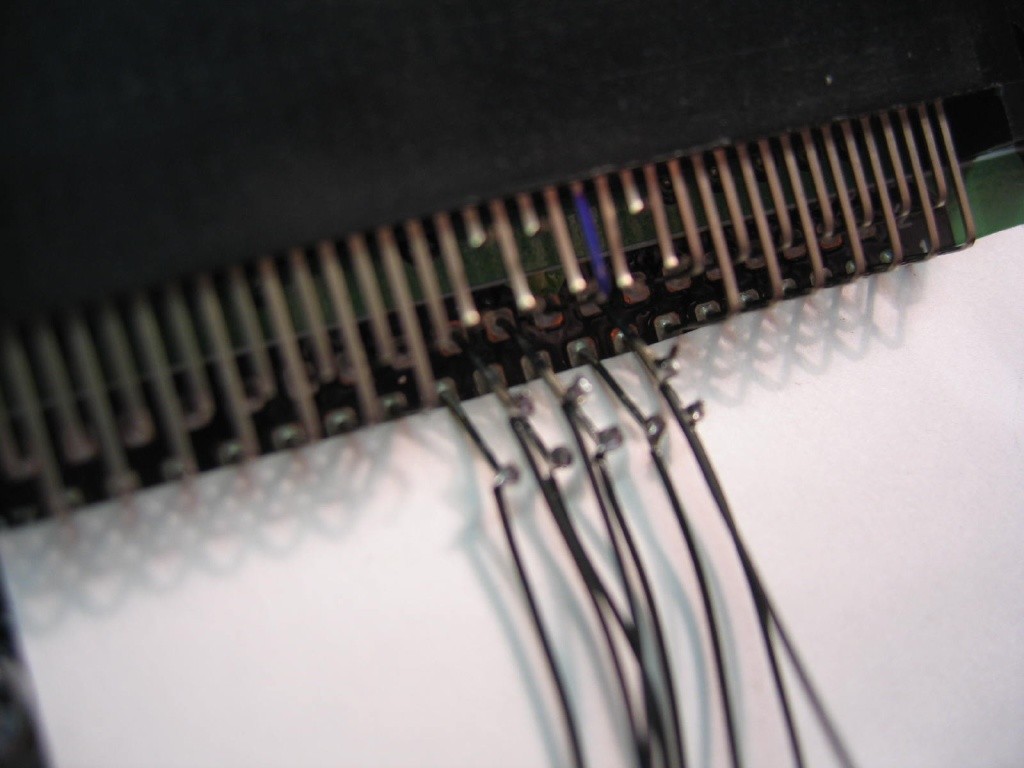
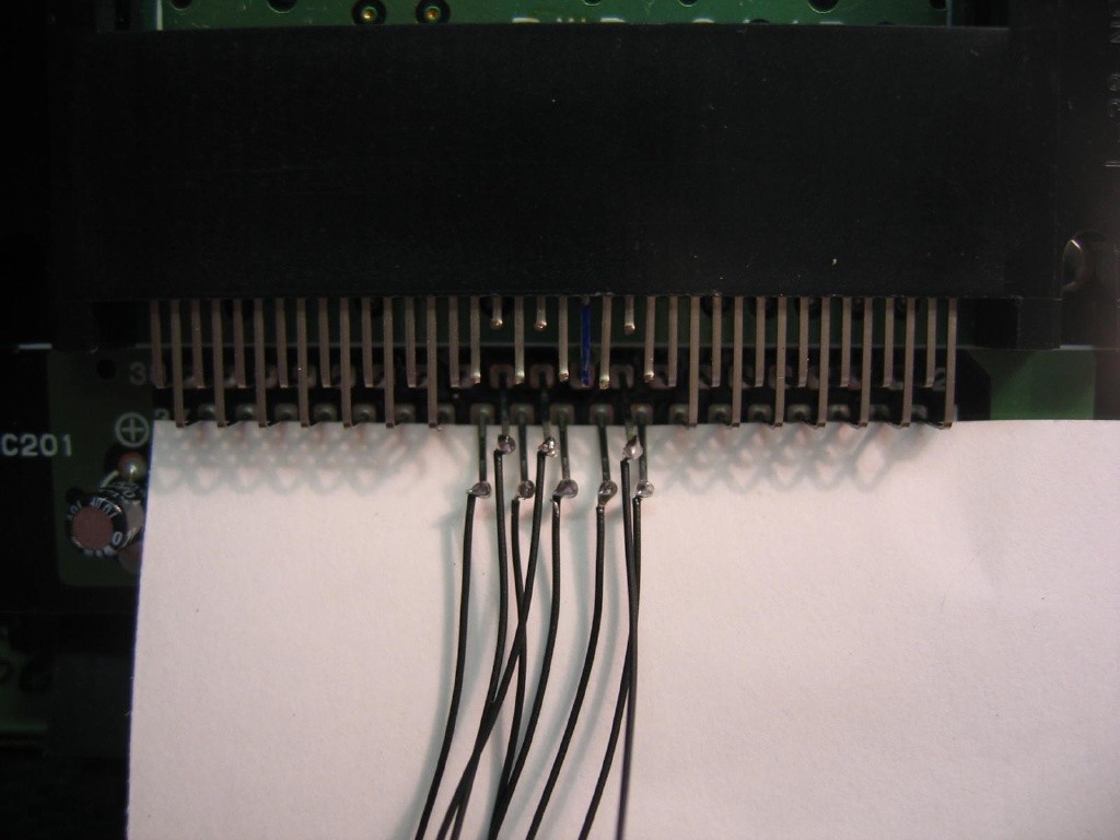
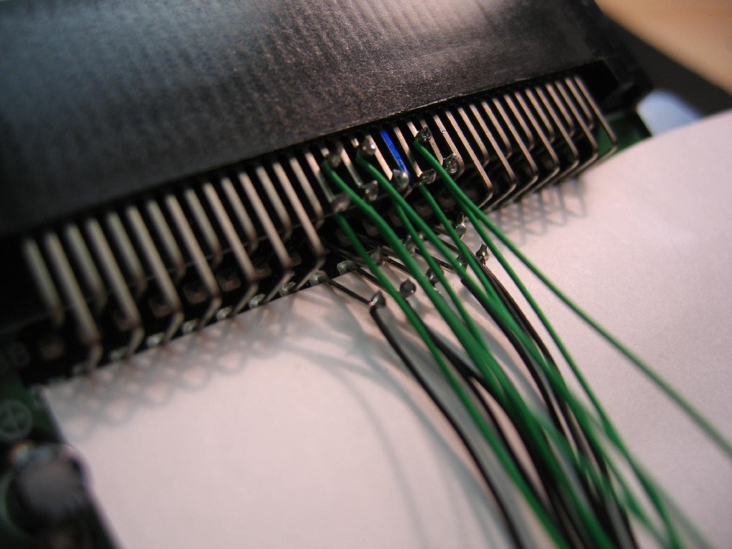
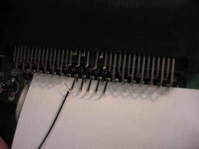
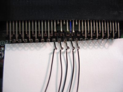
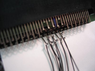
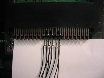
Now it's time to ante up and start wiring the pins up. Take the looped wire and hook it on a pin. While pulling a bit on the wire to give tension, use the screwdriver and massage the wire end around the pin so it wraps around and is snug. Doesn't have to be tight because we're going to solder it down. You can either solder each one after you wrap the wire or you can do what I do and go in rows. I do the bottom 5 pins first, closest to the PCB, then the next three, then the longer 5 on the cart slot side, and finally the short 3 pins closest to the black of the cart slot. Going in that order the wires won't overlap and get in your way. Remember, to solder the tip, hold the soldering iron to the wire/pin junction for a few seconds and then touch the backside (not next to the soldering iron but on the opposite side of the wire/in) with the solder itself. Now for 6 pictures of the progression of wire installation.


OK, now we're ready for the region PCB attachment. Head on over to Page 2 of this guide....